-
Introduction of manufacturing process
Gas turbines combust natural gas to generate high-temperature exhaust gas.
- 1External air is compressed by an air compressor to provide combustion air.
- 2In the combustor, air is mixed with fuel (natural gas) and ignited.
- 3The combustion gas rotates the turbine connected to the generator.
- 4Power is generated in the generator connected to the turbine.
- 5The gas turbine is rotated, and the exhaust gas that exits through the exhaust duct is sent to the heat recovery steam generator.
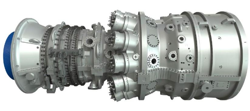
Gas TurbineINTRODUCTION OF MANUFACTURING FACILITIES- Manufacturer and Model
- GE Energy PG6111FA
- Single
- 3 Stages
- Inlet Temperature
- 1327℃
- Outlet Temperature
- 605℃
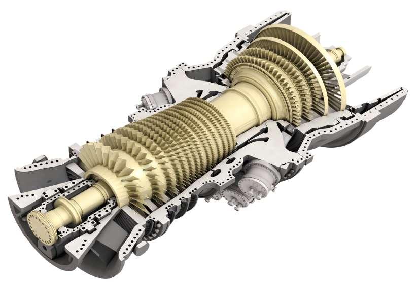
Gas Turbine & Compressor
CompressorINTRODUCTION OF MANUFACTURING FACILITIES- Type
- Axial Flow
- Single
- 18 Stages
- Compression Ratio
- 15.8
- Air Volume
- 196 kg/s
Gas Turbine & Compressor
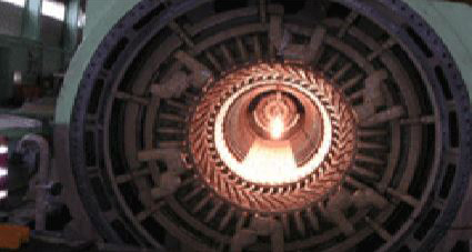
BurnerINTRODUCTION OF MANUFACTURING FACILITIES- Type
- Can Annular
- Burners
- 6 (DLN 2.6)
- Fuel Volume
- 17 ton/h
Burner
GeneratorINTRODUCTION OF MANUFACTURING FACILITIES- Type
- 3-Phase 2-Pole Air Cooling Type
- Capacity
- 76.9 MW (ISO)
- Power Factor
- 0.9
- Frequency
- 60.0 Hz
- Voltage
- 13.8 kV
Generator
View Facility Specifications within the Process Go to the Process
-
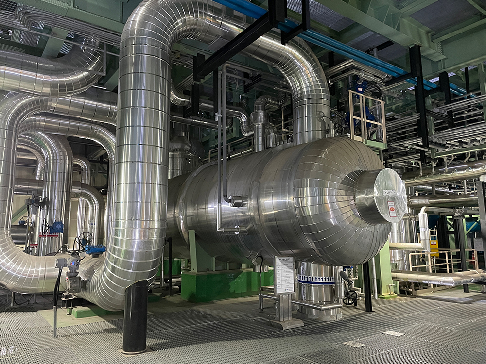
Introduction of manufacturing process
Heat recovery steam generator utilizes the heat from gas turbine exhaust gases to generate steam.
- 1The high-temperature exhaust gases discharged from the gas turbine are directed into the heat recovery steam generator.
- 2Heat recovery steam generator uses gas turbine exhaust gases to produce steam, which is then sent to either a steam turbine or a district heating water heater.
HRSGINTRODUCTION OF MANUFACTURING FACILITIES- Type
- Natural Circulation Horizontal Type
- Steam Generation Capacity
- 180 ton/h
- Inlet Temperature
- 565℃
- Steam Temperature
- 530℃ (Single Pressure)
Generator
View Facility Specifications within the Process Go to the Process
-
Introduction of manufacturing process
It generates electricity using steam and also heats using the generated heat.
- 1The high-pressure steam is used to rotate a turbine, and the resulting steam is directed to a district heating water heater.
- 2The steam that comes out after turning the turbine is converted into water as it passes through the heating water heater.
Steam TurbineINTRODUCTION OF MANUFACTURING FACILITIES- Type
- Impulse
- Single
- 11 Stages
- Steam Temperature
- 530℃
- Number of revolutions
- 3600rpm
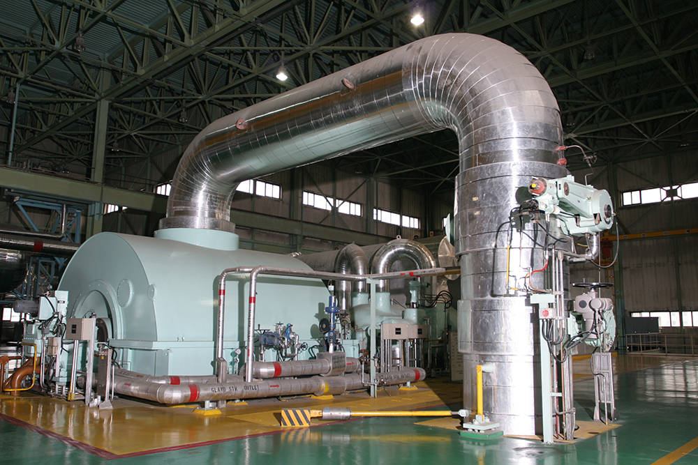
Steam Turbine
GeneratorINTRODUCTION OF MANUFACTURING FACILITIES- Type
- 3-Phase 2-Pole Air-Cooled
- Capacity
- 52.62 MW
- Power Factor
- 0.9
- Frequency
- 60.0 Hz
- Voltage
- 13.8 kV

Generator
DH Heat ExchangerINTRODUCTION OF MANUFACTURING FACILITIES- Type
- Shell (Steam) / Tube (Water)
- Inlet Temperature
- 65℃
- Outlet Temperature
- 120℃
- Heat Output
- Mode Ⅰ (170 Gcal/h)
Mode Ⅳ (211 Gcal/h)
Normal(170 Gcal/h)
Peak(211 Gcal/h)
DH Heat Exchanger
Cooling TowerINTRODUCTION OF MANUFACTURING FACILITIES- Type
- Air-cooler
- Quantity
- 4 CELLS
- Capacity
- 216.4 ton/h
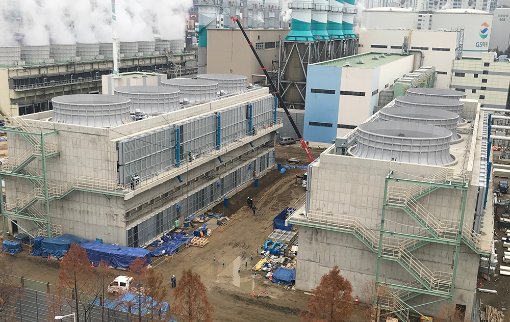
Cooling Tower
View Facility Specifications within the Process Go to the Process
-
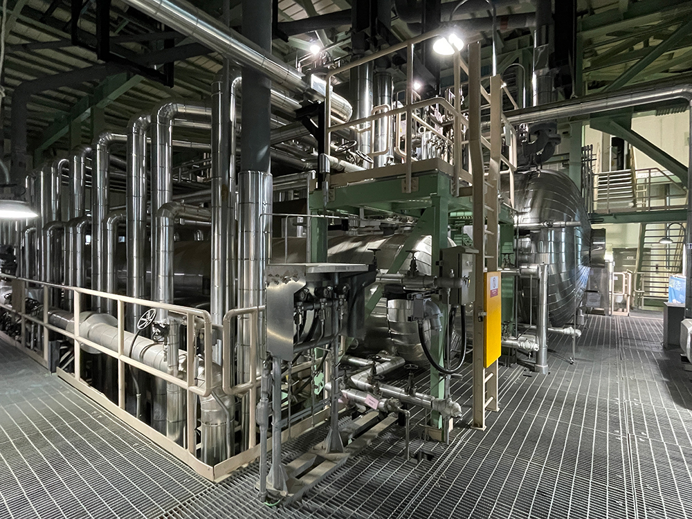
Introduction of manufacturing process
It produces 115°C heating water using the 1st, 2nd, and 3rd heat exchangers.
- 1The remaining heating water, used for district heating, is sent to the 1st, 2nd, and 3rd heat exchangers.
- 2Hot steam is supplied from the steam turbine.
- 3The hot steam is passed through the heating water heater to heat the heating water.
- 4The heat of the heating water is supplemented by the heat generated from the LNG boiler and incineration plant.
- 5The remaining heat in the heat accumulator is stored or used to supplement any heat shortage, and it is delivered to district heating users.
Boiler FacilityINTRODUCTION OF MANUFACTURING FACILITIES- Peak load boilers
- (Fuel: LNG) 103 Gcal/h 2 Units
It is a facility that produces heat required for district heating supply and consists of a combustion device, ventilation device, water supply/fuel supply device, automatic control device, stack, etc., and heats district heating hot water.
It is a facility that produces heat required for district heating supply and consists of a combustion device, ventilation device, water supply/fuel supply device, automatic control device, stack, etc., and heats district heating hot water.
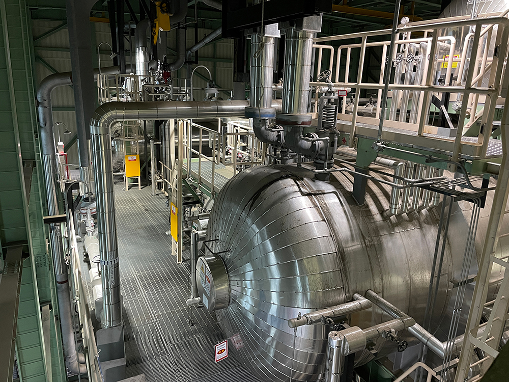
AccumulatorINTRODUCTION OF MANUFACTURING FACILITIES- Accumulator
- 30,000 ㎥ x 1 Unit
It is a facility for temporarily storing the heat required for supplying district heating. During periods of low heat demand, it stores heat and supplies it during times of high heat demand, ensuring the flexible operation of heat production facilities and maintaining the appropriate pressure for the entire district heating pipeline network. In case of a breakdown in heat production facilities, it also serves as an emergency heat source.
Heat storage Stored during low heat demand periods
Heat release Supplied during high heat demand periods
-
This is a facility that temporarily stores the heat required for district heating supply. It stores the heat during times of low heat demand and supplies it during times of high heat demand, thereby maintaining flexible operation of the heat production facility and maintaining appropriate pressure throughout the district heating heat piping. It is also used as an emergency heat source when heat production equipment malfunctions.
Heat storage_Stored during low heat demand periods
Heat release_Supplied during high heat demand periods
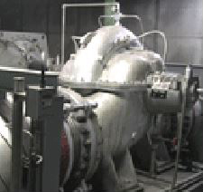
PumpINTRODUCTION OF MANUFACTURING FACILITIES- Supply Pump
- It operates for smooth heat supply during the winter season.
3 Units 4,700㎥/hr x 3
- Type
- It operates to produce heating heat from heat production (1st and 2nd heating water heaters, hot water/heat-exclusive boilers).
3 Units 4,700㎥/hr x 1 (Spare Pump)
2,200㎥/hr x 2
4,000㎥/hr x 2
- Pump for Heat Release or Accumulation
- It operates during heat release or accumulation
2 Units 2,000㎥ /hr x 2
-
Pump for Heat Release or Accumulation : It operates during heat release or accumulation
- Anyang
- 3 Units 1,000 ㎥/hr X 3
- Bucheon
- 3 Units 3,150㎥/hr X 3 (DH펌프동)
View Facility Specifications within the Process Go to the Process
-
Introduction of manufacturing process
It supplies hot water from the user's mechanical room to each household or office.
- 1Using hot water supplied from Incheon Total Energy at temperatures ranging from 75°C to 115°C, heating and hot water for each home and office are heated through heat exchangers installed in the mechanical room.
- 2The cooled heating water used in each home and office is recovered to the mechanical room, reheated through the heating heat exchanger, and supplied again.
- 3The hot water used is supplied to each home and office by heating tap water through heat exchanger.
- 4Inside the mechanical room, heat exchangers for heating and hot water are installed, and there are various heat usage facilities such as automatic control systems and pumps.
Plate type Heat ExchangerINTRODUCTION OF MANUFACTURING FACILITIESView Facility Specifications within the Process Go to the Process